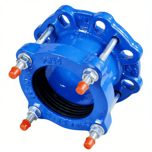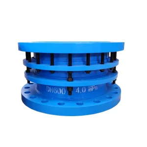
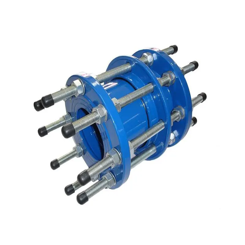
Double Flange Force-Transmitting Dismantling Joint — Sleeve Type (C2F)
DEVEL B2F double flange dismantling joint absorbs axial movement and locks pressure thrust for safe valve/pump maintenance. GB/T 12465-2017, DN65–DN3600.
- Axial travel ±25–90 mm — absorbs thermal expansion and pipe settlement
- Limit rods restrain pressure thrust — protects pump nozzles and valve bodies
- Dismantling gap up to 90 mm — remove valves and meters without pipe cutting
- Multi-material — carbon steel, WCB, ductile iron, 304/316L stainless
- 1.5× strength test, 4× burst test — certified zero leakage
Contact Us for Pricing
Interested in this product? Contact us now for detailed pricing and product information.
Product Details
DEVEL Double Flange Force-Transmitting Dismantling Joints (C2F type) are compact steel sleeve joints designed to transfer axial pressure thrust between flanged pipe ends while allowing the sleeve to be retracted for valve and equipment removal. Manufactured to GB/T 12465-2017, available DN65–DN3200 with PN6/PN10 rating, in carbon steel, WCB, ductile iron, 304 and 316L.
What Is a C2F Dismantling Joint and When to Specify It
DEVEL Double Flange Force-Transmitting Dismantling Joints — also referred to as C2F sleeve joints, gland-packed dismantling joints, or force-transmitting expansion joints — are rigid steel pipe connectors engineered to transfer axial pressure thrust between two flanged pipe ends while providing a limited retractable stroke for installation and equipment removal.
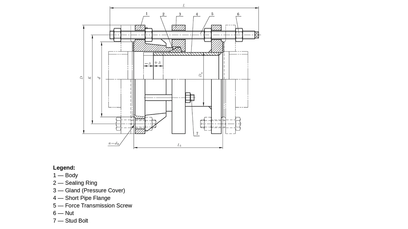
Unlike the B2F limited expansion joint (which uses a telescoping limit expansion pipe and limit rods to absorb axial movement), the C2F uses a short pipe flange and force-transmitting screws that rigidly lock the two halves together. The result is a joint that does not compensate for ongoing thermal expansion — instead, it functions as a structural load-carrying connector with a dismantling function: retract the screws, compress the sleeve, and a valve, pump, or flow meter can be pulled out of the line without cutting or re-welding the pipe.
This makes the C2F the preferred choice where the pipeline is already stress-compensated by a separate expansion joint, equipment must be withdrawn axially for maintenance, a shorter face-to-face length is required than a B2F can offer, or a more economical alternative is needed where displacement compensation is not required. As a factory-direct manufacturer, DEVEL supplies C2F joints in full compliance with GB/T 12465-2017, covering DN65 to DN3200 in PN6 and PN10 ratings.
Key Features of the C2F Dismantling Joint
- Positive Pressure Thrust Transfer Without Limit Rods
The C2F’s force-transmitting screws act as structural tension members, carrying the full hydraulic end-load (pressure × cross-sectional area) from one flange to the other. At PN10 and DN600, that load exceeds 280 kN — the C2F transfers it directly, protecting adjacent pump nozzles, valve bodies, and thin-wall equipment from axial thrust damage. Unlike the B2F, there is no telescoping limit expansion pipe; the joint is functionally rigid once the screws are locked. - Dismantling Function for Valve and Equipment Maintenance
By loosening the force-transmitting screws on one side and compressing the gland-packed sleeve, the C2F creates a clearance gap that allows a valve, flow meter, strainer, or pump to be removed axially without cutting or re-welding the pipeline. This is the primary reason C2F joints are specified in water treatment plants, district heating networks, and refinery process lines where hot-work permits are costly and downtime must be minimized. - Compact Face-to-Face — 30–40 % Shorter Than B2F
Because the C2F has no telescoping limit expansion pipe, its overall length is significantly shorter than the equivalent B2F. For example, at DN200 a typical C2F measures ~210 mm face-to-face versus ~380 mm for a B2F. This makes the C2F ideal for retrofit projects with limited pipe spacing, skid-mounted equipment packages, and compact valve manifolds. - Gland-Packed Seal for Reliable Re-Seating
The seal between the body and the short pipe flange is achieved through a gland compression ring packed with a replaceable sealing element (NBR, EPDM, silicone, or PTFE-encapsulated per medium). When the sleeve is retracted for maintenance and re-compressed, the gland is simply re-torqued — no replacement of the entire joint is required. - Certified Pressure Integrity — 1.5× Strength Test and 4× Burst Test
Every C2F joint undergoes a hydrostatic strength test at 1.5 times rated working pressure for 5 minutes (zero leakage, zero plastic deformation). A batch sample is further subjected to a burst test at 4 times rated pressure for 5 minutes. Length tolerances ±5 mm, flange perpendicularity 1% DN (≤4 mm), coaxiality 1% DN (≤5 mm) — in full compliance with GB/T 12465-2017 §5.4–5.6.
Technical Parameters & Material Specifications
| Technical Property | Specification |
|---|---|
| Product Name | Double Flange Sleeve Force-Transmitting Dismantling Joint (C2F) |
| Standard Compliance | GB/T 12465-2017 (Pipe Compensation Joints) |
| Nominal Diameter (DN) | DN65 – DN3200 |
| Working Pressure | PN6 / PN10 |
| Operating Temperature | ≤ 170 °C (continuous) |
| Axial Retraction Stroke | Limited — for installation and dismantling only (not for in-service compensation) |
| Body / Gland / Short Pipe Flange Material | Q235, 20 steel, WCB, QT400-15, QT450-10, 06Cr19Ni10 (304), 022Cr17Ni12Mo2 (316L) |
| Seal Ring Material | NBR, EPDM, Silicone, PTFE-encapsulated (media dependent) |
| Force-Transmitting Screw / Stud Material | Q235A, 35 steel, 45 steel, 304 / 316L stainless |
| Surface Coating | Hot-dip galvanized (standard), epoxy, plastic coated, nickel plated |
| Flange Drilling | GB, ASME B16.5, DIN, BS EN 1092, JIS — custom available |
| Strength Test | 1.5 × rated pressure, 5 min hold, zero leakage |
| Burst Test | 4 × rated pressure, 5 min hold, zero visible cracking |
| Safety Factor | ≥ 4:1 (burst vs. working pressure) |
Material & Coating Selection Guide
The C2F joint uses the same material and coating system as the B2F. Select body material, seal material, and surface coating based on the service medium and installation environment:
Body Material Selection
| Code | Material | Best For | Limitations |
|---|---|---|---|
| G | Carbon steel (Q235) | General industrial water, HVAC, compressed air | Not for buried service without coating |
| ZG | Cast steel WCB | Higher pressure, steam, hot oil | Higher cost; heavier |
| Q | Ductile iron QT400-15 | Buried municipal water, sewage, potable water | Not for high-temperature steam |
| N | 06Cr19Ni10 (304 SS) | Seawater, food, pharmaceutical, mild chemicals | Pitting risk in stagnant chloride service |
| N1 | 022Cr17Ni12Mo2 (316L SS) | Chemical, marine, desalination, high-chloride | Premium cost |
Seal Ring Material Selection
| Seal Material | Temperature Range | Best For | Avoid For |
|---|---|---|---|
| NBR | −15 °C to +100 °C | Oils, fuels, compressed air, water | Ozone, strong oxidizers, UV |
| EPDM | −20 °C to +150 °C | Hot water, steam, cooling water, potable water | Petroleum-based fluids |
| Silicone | −40 °C to +200 °C | High-temperature air, food and pharmaceutical | High pressure, petroleum |
| PTFE-encapsulated | −30 °C to +180 °C | Strong acids, alkalis, solvents, aggressive chemicals | Low-pressure-only; costly |
Surface Coating Selection
| Code | Coating | Typical Application |
|---|---|---|
| Z | Hot-dip galvanized | Standard for above-ground and sheltered outdoor service |
| S | Plastic coated (PE/epoxy) | Buried pipelines, aggressive soil, water and sewage |
| N | Nickel plated | Food, pharmaceutical, decorative / clean-in-place service |
| H | Epoxy coated | Potable water, chemical plants, marine environments |
Not sure which combination fits your project? Our engineers can recommend the correct body, seal, and coating combination based on your medium, temperature, pressure, and installation environment. Contact us for technical support →
C2F Dimensional Reference (PN6)
Values below are representative face-to-face lengths per GB/T 12465-2017 Table 16. Final dimensions confirmed at quotation (±5 mm). PN10 table available on request.
| DN (mm) | Inch | L (mm) | D (mm) | K (mm) | n–d₀ | Mass (kg) |
|---|---|---|---|---|---|---|
| 65 | 2.5 | 200 | 160 | 130 | 4–M12 | 9.5 |
| 80 | 3 | 210 | 190 | 150 | 4–M16 | 12.5 |
| 100 | 4 | 220 | 210 | 170 | 4–M16 | 16.0 |
| 125 | 5 | 230 | 240 | 200 | 8–M16 | 21.0 |
| 150 | 6 | 240 | 265 | 225 | 8–M16 | 27.0 |
| 200 | 8 | 260 | 320 | 280 | 8–M16 | 41.0 |
| 250 | 10 | 280 | 375 | 335 | 12–M16 | 57.0 |
| 300 | 12 | 300 | 440 | 395 | 12–M20 | 76.0 |
| 350 | 14 | 320 | 490 | 445 | 12–M20 | 98.0 |
| 400 | 16 | 340 | 540 | 495 | 16–M20 | 122.0 |
| 450 | 18 | 360 | 595 | 550 | 16–M20 | 148.0 |
| 500 | 20 | 380 | 645 | 600 | 20–M20 | 178.0 |
| 600 | 24 | 420 | 755 | 705 | 20–M24 | 255.0 |
| 700 | 28 | 460 | 860 | 810 | 24–M24 | 335.0 |
| 800 | 32 | 500 | 975 | 920 | 24–M24 | 430.0 |
| 900 | 36 | 540 | 1075 | 1020 | 24–M27 | 540.0 |
| 1000 | 40 | 580 | 1175 | 1120 | 28–M27 | 665.0 |
| 1200 | 48 | 660 | 1375 | 1320 | 32–M27 | 960.0 |
| 1400 | 56 | 740 | 1575 | 1520 | 36–M27 | 1320.0 |
| 1600 | 64 | 820 | 1785 | 1730 | 40–M27 | 1750.0 |
L = total face-to-face length at installed (locked) position; D = flange outer diameter; K = bolt circle diameter; n–d₀ = number of bolts × bolt size. The C2F does not have an in-service axial movement rating — sleeve retraction is for installation and dismantling only.
DN1800–DN3200 and PN10 dimensional data available on request. Contact us →
C2F vs. B2F — Choosing the Right Dismantling Joint
| Feature | C2F (Force-Transmitting) | B2F (Limited Expansion) |
|---|---|---|
| Internal component | Short pipe flange | Telescoping limit expansion pipe |
| Tie member | Force-transmitting screws (rigid) | Limit rods (with travel allowance) |
| In-service axial movement | None — rigid when locked | Yes — ±δ (25–90 mm depending on DN) |
| Dismantling function | Yes — retract screws to compress sleeve | Yes — retract limit rods to compress sleeve |
| Face-to-face length | Shorter (~30–40 % less than B2F) | Longer |
| Cost | More economical | Higher |
| Best for | Rigid removable connections where expansion is handled elsewhere | Connections needing both movement compensation and dismantling |
Need a joint that also absorbs axial movement? See our B2F Double Flange Dismantling Joint — it combines dismantling function with ±δ displacement compensation.
Industries and Applications
- Municipal Water & Wastewater: Valve chambers, pump stations, and metering vaults where valves and flow meters must be withdrawn for servicing without disturbing the pipe.
- Power Generation: Condenser isolation, cooling water pump connections, and auxiliary equipment spools — the C2F’s rigid load transfer protects pump nozzles from thrust loads.
- Desalination & Marine: Seawater intake screens, filter vessels, and high-pressure pump inlets — 316L stainless steel construction with EPDM or PTFE seals handles chloride service reliably.
- Oil & Gas Terminals: Pipeline scraper trap connections, metering skid isolation, and tank farm manifold valves — WCB or carbon steel with hot-dip galvanized coating for long-term outdoor service.
- District Heating & HVAC: Heat exchanger connections, boiler feed pump isolations, and distribution main valve chambers — EPDM seals handle continuous operation up to 150 °C.
- Industrial Process Piping: Chemical plants, pulp and paper, food and beverage — material combinations available for nearly any neutral or aggressive medium up to 170 °C.
How to Specify a C2F Dismantling Joint — Marking System
GB/T 12465-2017 defines a structured marking system shared across all joint types. A complete C2F order code contains all critical parameters:
Example: C2F-6900-G-Z — C2F type, PN6, DN900, carbon steel body (G), hot-dip galvanized (Z).
When requesting a quotation, please provide:
- Nominal diameter (DN) and pressure rating (PN6 or PN10)
- Body material code (G, 20, ZG, Q, Q1, N, N1)
- Seal material (NBR, EPDM, Silicone, PTFE)
- Surface coating (Z, S, N, H)
- Flange drilling standard (GB, ASME, DIN, JIS, BS EN 1092)
- Face-to-face length if non-standard (default per table above)
Installation and Commissioning Notes
- Pipe Preparation: Clean both mating flange faces. Verify flange alignment — the C2F is a rigid joint and does not tolerate angular or lateral misalignment. Correct any pipe offset before installation.
- Install at Locked Position: Install the joint with the force-transmitting screws fully extended to the neutral (installed) position. Do not pre-load the sleeve in compression or tension.
- Bolt-Up Sequence: Torque the main flange studs in a cross-pattern to the specified torque for the flange size and pressure rating. Then torque the force-transmitting screw nuts evenly to lock the sleeve in position.
- Pressure Test: Hydrostatic test the system at 1.5 × working pressure before commissioning. Inspect all gland bolts and force-transmitting screw nuts for tightness after the test.
- Dismantling for Maintenance: To remove downstream equipment, loosen the force-transmitting screws on the equipment side and compress the sleeve toward the body. Re-torque the gland bolts after reassembly.
Frequently Asked Questions
What is the difference between C2F and B2F dismantling joints?
Both are double-flange steel sleeve joints under GB/T 12465-2017. The B2F has a telescoping limit expansion pipe and limit rods, allowing it to absorb axial movement (±δ) in service while also providing a dismantling function. The C2F has a short pipe flange and rigid force-transmitting screws — it does not absorb in-service axial movement, but is shorter, simpler, and more economical.
Can a C2F joint replace a fixed flange spool piece?
Yes — and that is one of its primary use cases. A C2F installed between a valve and the pipeline functions exactly like a rigid flange spool during normal operation, but allows the valve to be withdrawn axially for maintenance without breaking the pipe.
Does the C2F compensate for thermal expansion?
No. The C2F is a rigid force-transmitting joint. If the pipeline requires thermal expansion compensation, a separate expansion joint (rubber, metallic bellows, or a B2F limited expansion joint) must be installed elsewhere in the line. The C2F can be used in series with a B2F: the B2F handles movement, the C2F provides the removable connection point.
What is the maximum temperature for a C2F joint?
The standard C2F is rated for continuous service up to 170 °C with appropriate seal selection (EPDM or PTFE-encapsulated). For higher temperatures, a metallic bellows expansion joint is recommended.
Do you offer C2F joints with ASME or DIN flanges?
Yes. While the body is manufactured to GB/T 12465-2017, the flange drilling can be supplied to ASME B16.5 (Class 150 / 300), DIN, BS EN 1092, or JIS standards to match your existing piping.
How long is the delivery time?
Standard sizes (DN65–DN600, PN6/PN10, carbon steel, hot-dip galvanized) typically ship within 7–10 working days. Larger sizes, stainless steel construction, or custom flange drilling require 3–6 weeks.
Looking for a compact, economical dismantling joint?
Contact DEVEL for factory-direct pricing on C2F double flange force-transmitting dismantling joints, DN65–DN3200, PN6/PN10. Carbon steel, WCB, ductile iron, and stainless steel constructions available. Request Factory Quote →
Tags: Double Flange Dismantling Joint, C2F Expansion Joint, Force-Transmitting Dismantling Joint, Gland Packed Dismantling Joint, Sleeve Force-Transmitting Joint, GB/T 12465-2017, Dismantling Joint, Pipe Compensation Joint, PN6 / PN10, DN65 – DN3200, Carbon Steel Dismantling Joint, Stainless Steel Dismantling Joint, Municipal Water, Power Plant Cooling, Desalination, Valve Isolation Joint, Rigid Pipe Connector